CDI Inverter Table of Contents
Meka Scoot Tuning’s CDI Inverter
Instructions for CDI INVERTER setup.
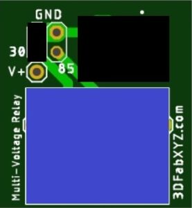
Tabs are located on the bottom of CDI Inverter:

It is important to note: Power going to the Relay must come from the Ignition Switch, this is to prevent the electronics in the relay from creating unwanted battery drain while the moped is not in use. The second point to note is that the pin 30 must be connected directly to ground (the ground coming from the Ignition Switch is disconnected when the key is disengaged).
Method #1:
On the top place a jumper between pins 30 and GND.

On the bottom:
Connect Tab 30 to the Black wire (Ground).
Connect Tab 85 to the White/Black wire (The wire between the Kill Switch and CDI unit. If the Kill Switch is removed connect to the White/Black wire coming from the Ignition Switch).
Connect Tab 86 to the Brown wire (Voltage Source coming from the Ignition Switch).
Connect Tab 87A to the White/Black wire (Going to CDI Unit).
Method #2:
On the top place a jumper between pins 30 and GND, and a jumper between pins 85 and GND.

Connect Tab 85 to the Black wire (Ground). Do not connect to the White/Black wire (Ground of CDI Kill Switch) as this wire goes through the ignition switch and is not connected directly to Ground.
Connect Tab 86 to the Brown wire (Voltage Source coming from the Ignition Switch).
Connect Tab 87A to the White/Black wire (Going to CDI Unit).
Please note: In this configuration the Kill Switch is not connected, therefore it is disabled.
Wiring diagram for MVT DD mod
This is the recommended basic wiring diagram for the Yamaha BWS Zuma 50 with the MVT DD. The Multi-voltage relay is used as a CDI inverter.
Example wiring diagram

Note: Parts Numbered 6, 8, 9, 10 and 11 are outlined in light blue, the upper box represents the OEM CDI unit and the lower box represents the after-market CDI unit (which requires an inverter).
IMPORTANT NOTICE FOR V3.0 BOARDS
The relays we received flip the outputs, the schematic diagram data and actual device have the outputs inverted.
Please note that for V3.0 boards the Pins 87A and 87 are inverted (Backwards).
All references for 87A should be 87 and all references for 87 should be 87A.
87A NC = Normally Open
87 NO = Normally Closed
** V4.0 Boards will follow industry standard as in the wiring diagram on this page.

